
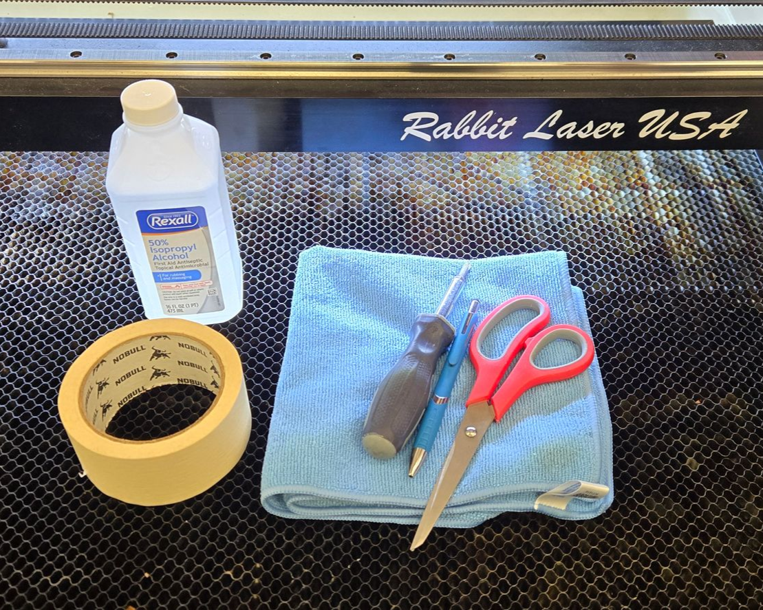
- 2” masking tape (paper tape works best)
- Scissors
- Pen or marker (dark color)
- Phillips screwdriver
- Mirror adjustment tool or fingers (depending on mounts)
- Paper towel
- Denatured alcohol (optional cleaning)
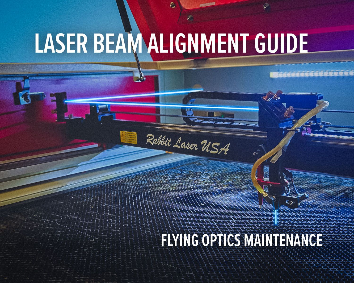
Laser Beam Alignment for Flying Optics Machines
A practical maintenance guide for consistent cutting and engraving
Laser alignment is one of the most important maintenance tasks on a flying optics machine. Even a small shift in the beam path can cause weak cuts, angled edges, power loss, or clipping inside the nozzle.
The good news is alignment is mechanical and repeatable. Once you understand the process, it becomes a straightforward maintenance routine.
This guide walks through a clean step-by-step alignment using the machine’s built-in pulse/test fire function and simple tools. No special equipment required.
Tools & Materials
Before You Begin
Alignment assumes:
- Laser tube fires normally
- Coolant is flowing
- Mirrors are clean
- Nothing inside the machine is loose
Only use short pulse bursts.
Keep all covers closed during firing.
Alignment must be done in order.
Mirrors are named:
- Mirror 1 — closest to the tube
- Mirror 2 — gantry mirror
- Mirror 3 — head mirror above the nozzle
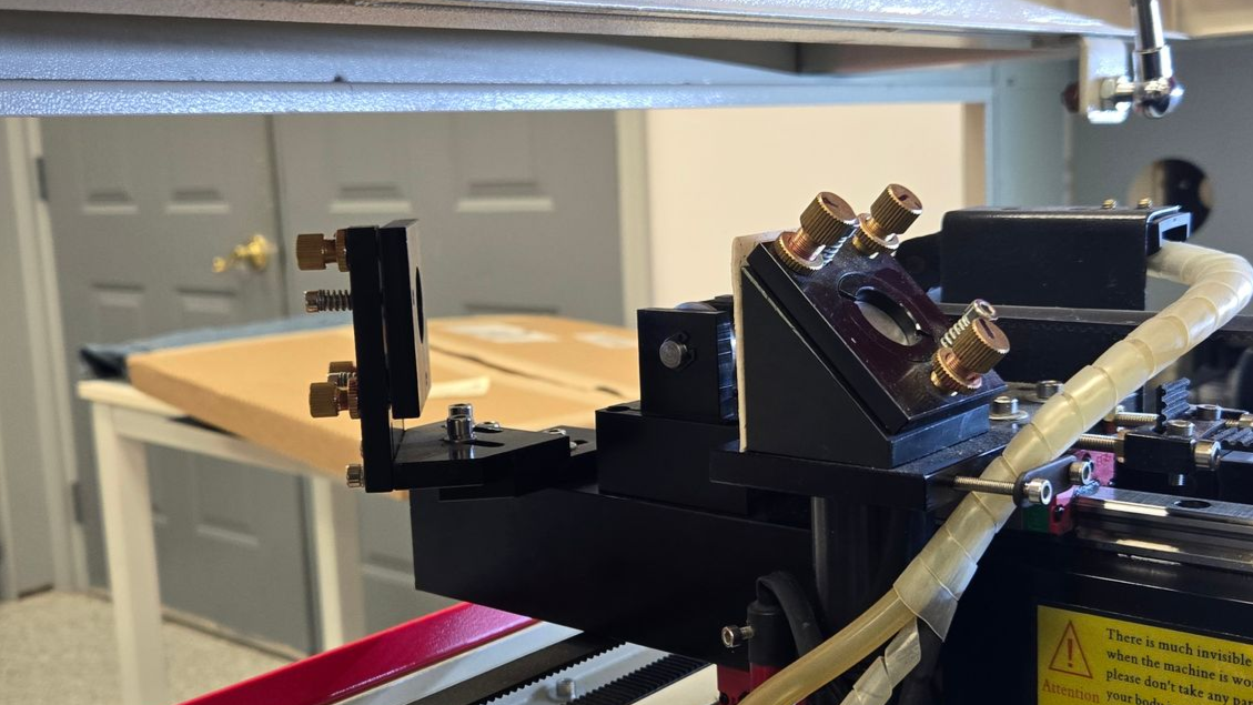
Phase 1 — Tube → Mirror 1 Check
Before adjusting anything, confirm the beam is entering mirror 1.
Open the rear compartment and visually inspect:
- Tube points directly at mirror 1
- No obstructions
- Path looks centered
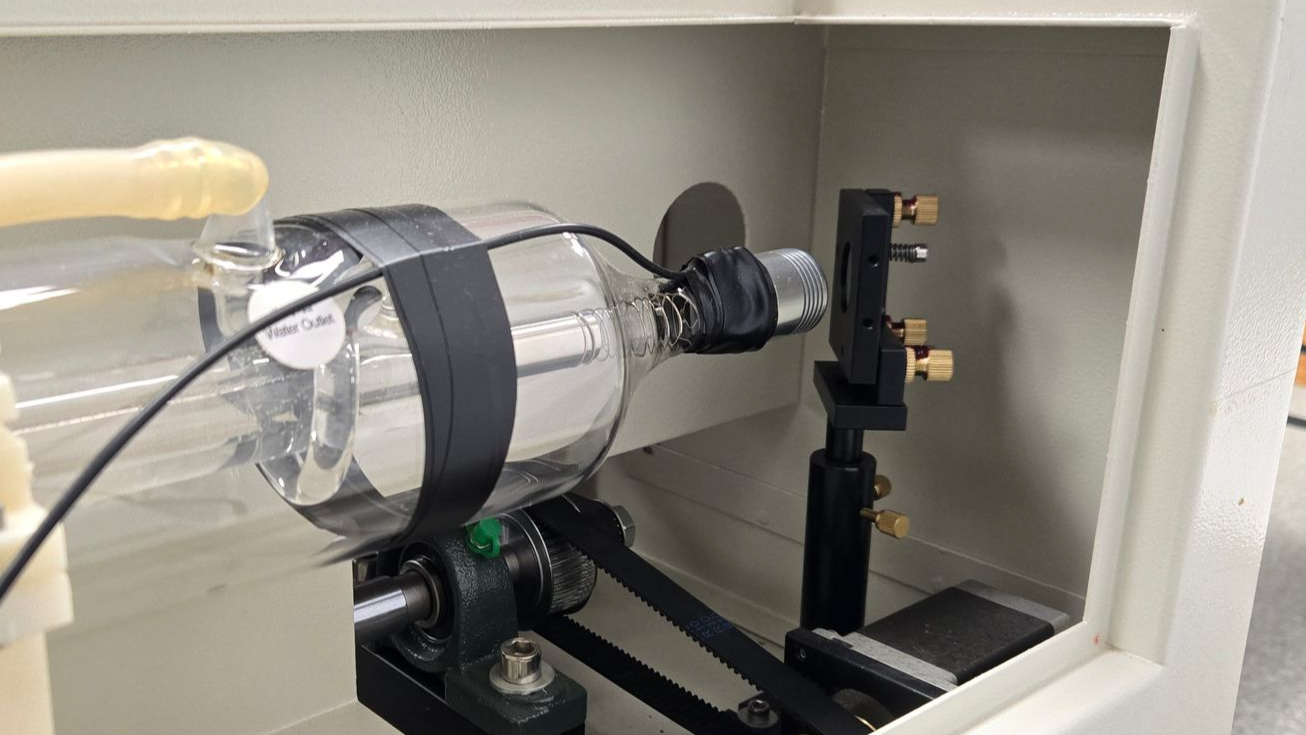
If the beam misses mirror 1 entirely, correct tube positioning first. Alignment cannot begin until the beam hits the first mirror.
Phase 2 — Mirror 1 → Mirror 2 Alignment
This aligns the beam along the Y-axis travel.
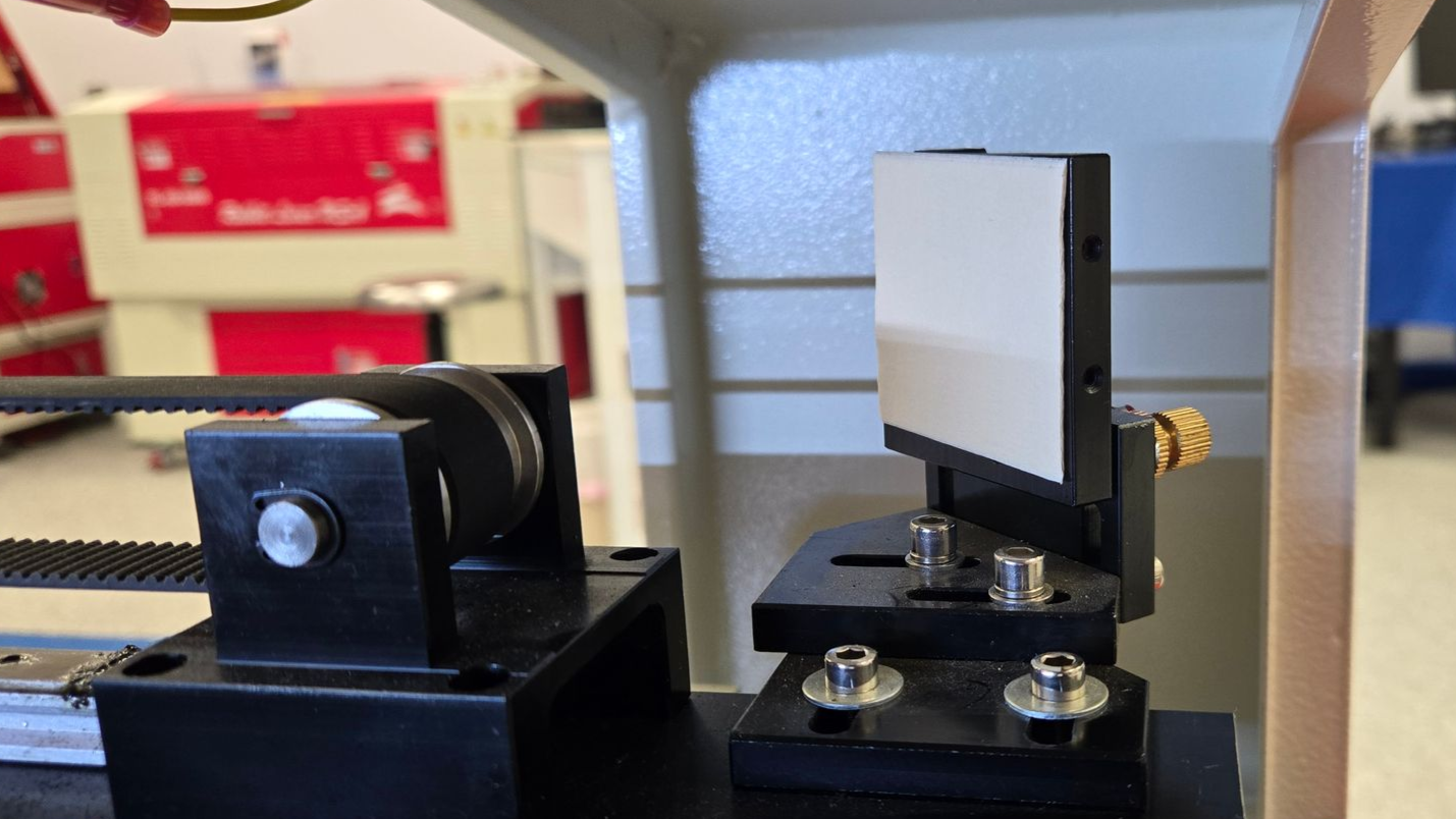
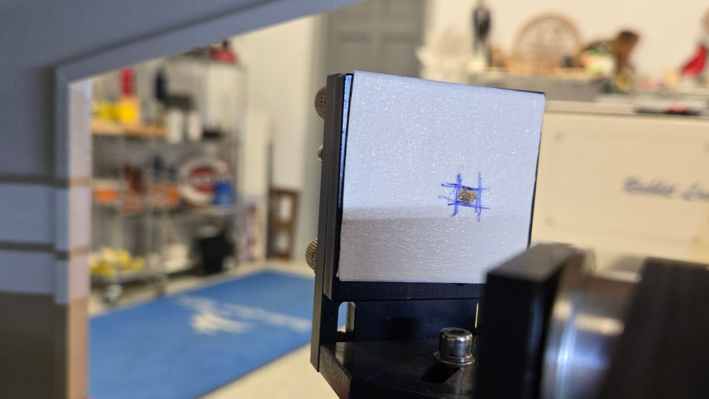
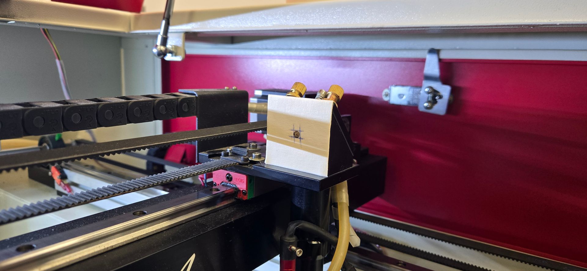
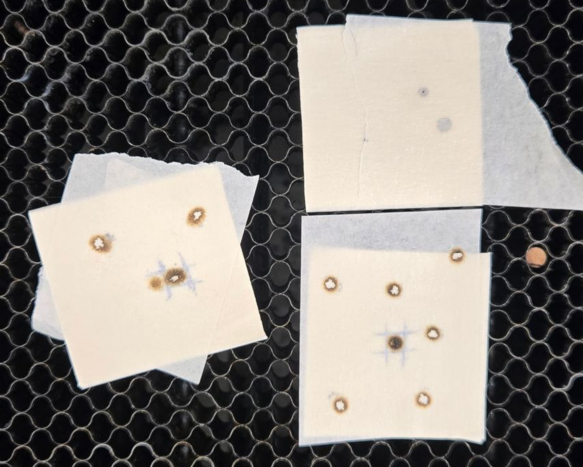
Step 1 — Create a Target
Layer masking tape into a thick pad (10–15 layers).
Place the target on the bracket of mirror 2.
The tape must not touch the mirror surface.
Step 2 — Rear Position Test
Move the gantry to the rear of the machine.
Close the lid and fire a short pulse.
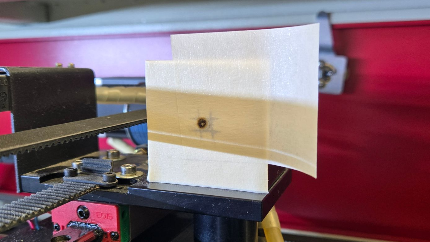
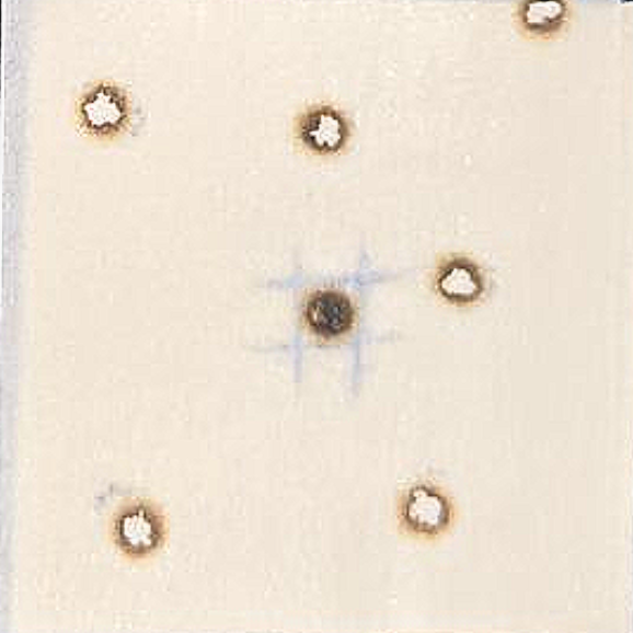
You should see a dark oval burn.
Mark the edges of the burn with a pen.
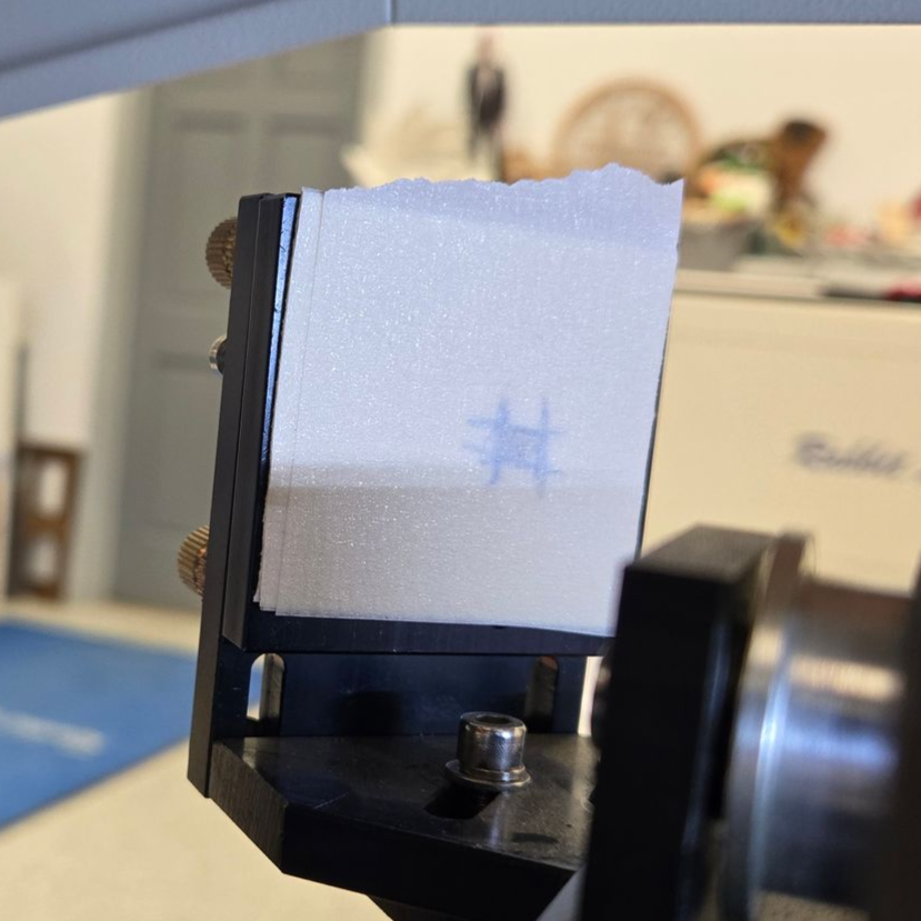
Step 3 — Front Position Test
Move the gantry to the front.
Cover the target with fresh tape.
Pulse again.
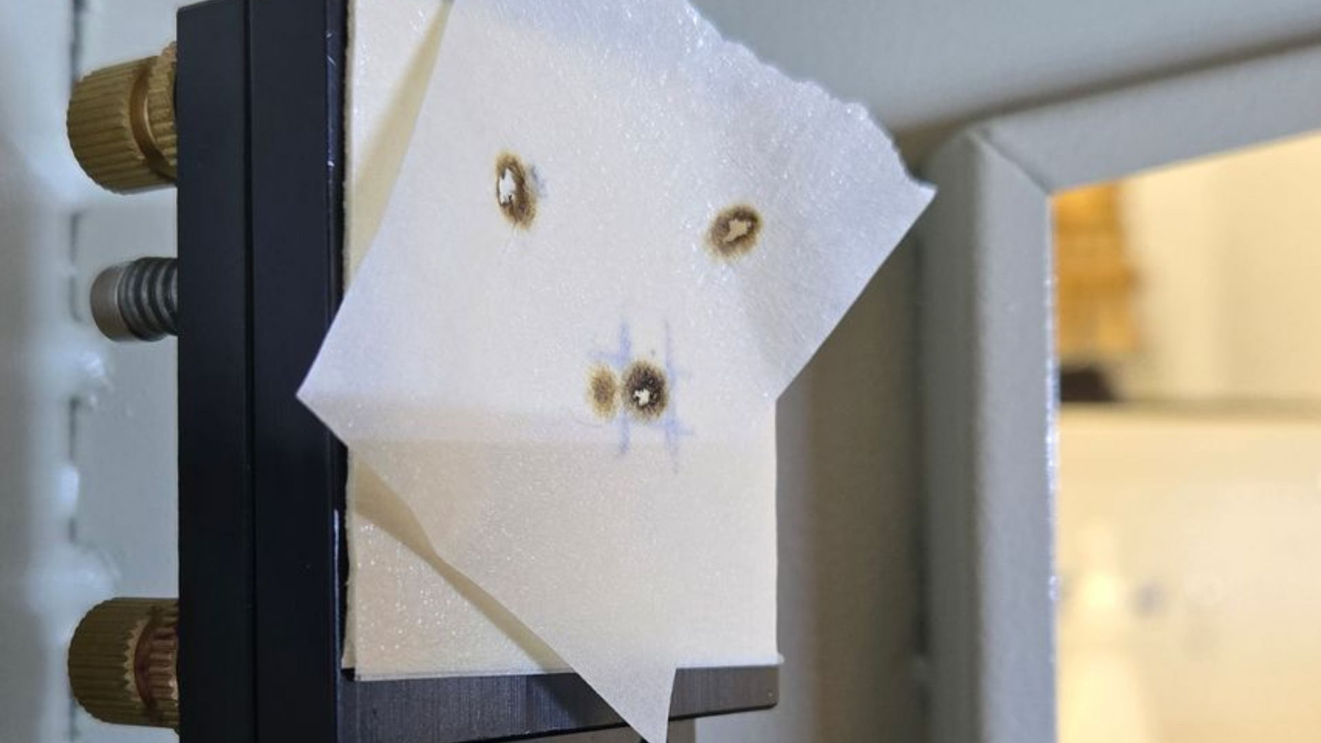
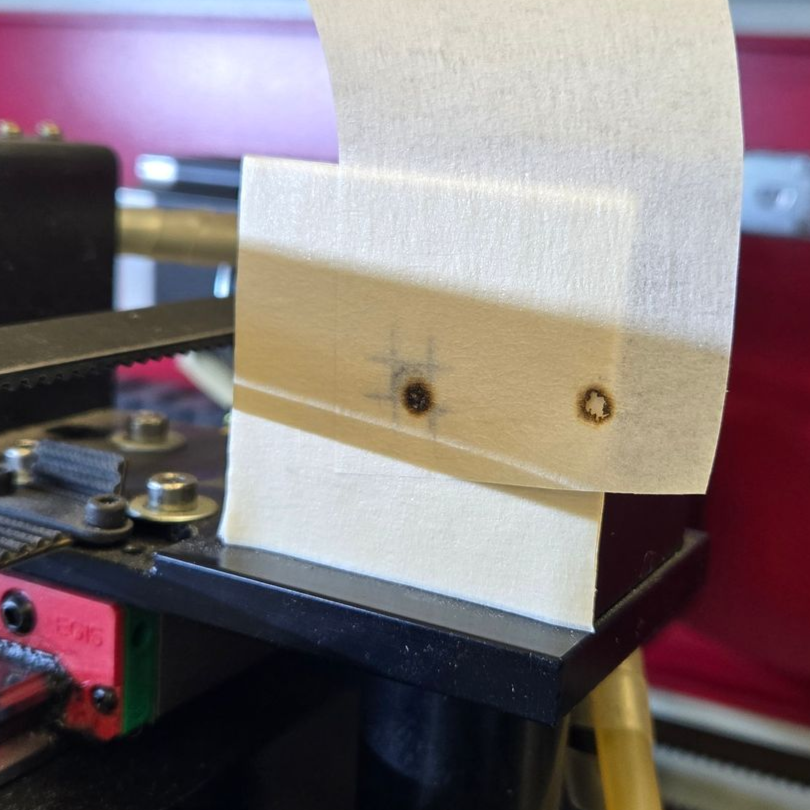
Compare the new burn to the original.
Step 4 — Adjust Mirror 1
If the two burns do not overlap:
Adjust mirror 1 screws slightly.
Use very small turns.
Even 1/16 turn can be enough.
Repeat rear → front testing until the burns land in the same spot.
Goal: identical burn location regardless of gantry position.
When the marks overlap, mirror 1 is aligned.
Phase 3 — Mirror 2 → Mirror 3 Alignment
This aligns the beam along the X-axis.
Step 1 — Move Target
Place a layered tape target on mirror 3.
Step 2 — Left Position Test
Move the head fully left.
Pulse once.
Mark the burn.
Step 3 — Right Position Test
Move the head fully right.
Cover with fresh tape and pulse again.
Step 4 — Adjust Mirror 2
Use mirror 2 screws.
Repeat left/right testing until the burns overlap.
When both positions match, mirror 2 is aligned.
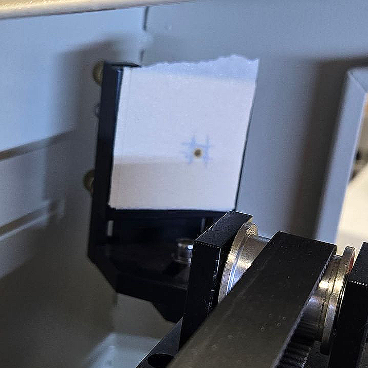
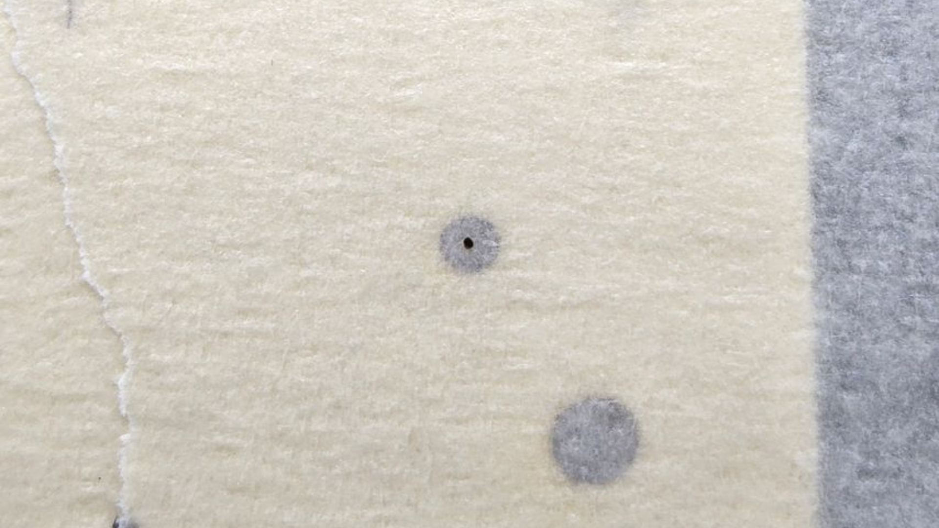
Phase 4 — Centering the Beam Into the Head
Place a 3-layer tape target over the entry hole of the head.
Trace the circular opening with a pen.
Move the head to the center of the table.
Pulse once.
The burn should be:
- centered in the circle
- slightly above center (normal)
If off-center:
Make fine adjustments to mirror 2 and mirror 3.
Repeat until centered and consistent.
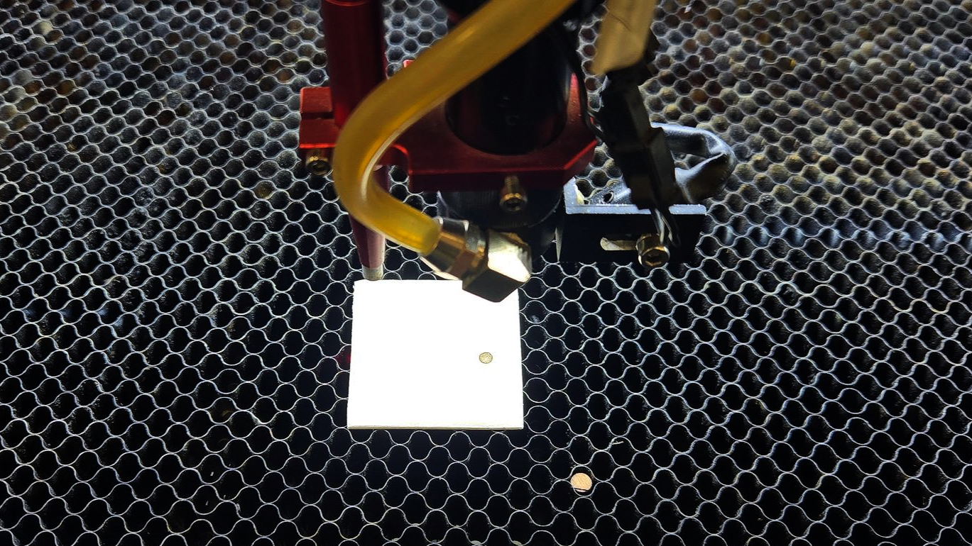
Phase 5 — Final Spot Check at the Table
Place tape flat on the work bed.
Lower the table slightly out of focus.
Pulse once.
You should see:
- a clean round spot
- smooth edges
- no crescent or clipping shape
If the spot looks distorted, the beam may be hitting the nozzle and requires minor adjustment.
Alignment Complete
Alignment is finished when:
- rear/front burns match
- left/right burns match
- head entry is centered
- final table spot is round
At this point the beam path is straight and consistent.
Quick Troubleshooting Guide
Burn shifts front to rear
→ Adjust mirror 1
Burn shifts left to right
→ Adjust mirror 2
Spot clips inside nozzle
→ Beam not centered into head
Weak cutting power
→ Alignment issue or dirty mirrors
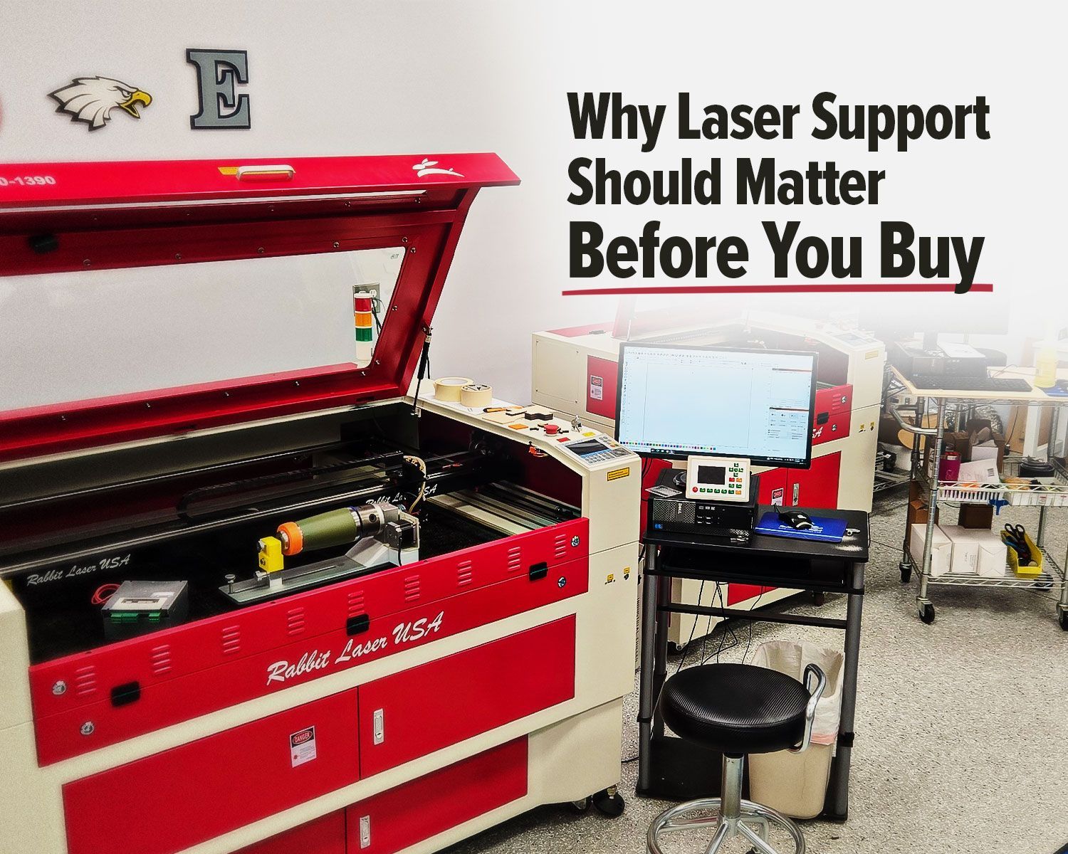
Rabbit Laser USA CO2 laser with support workstation for troubleshooting.
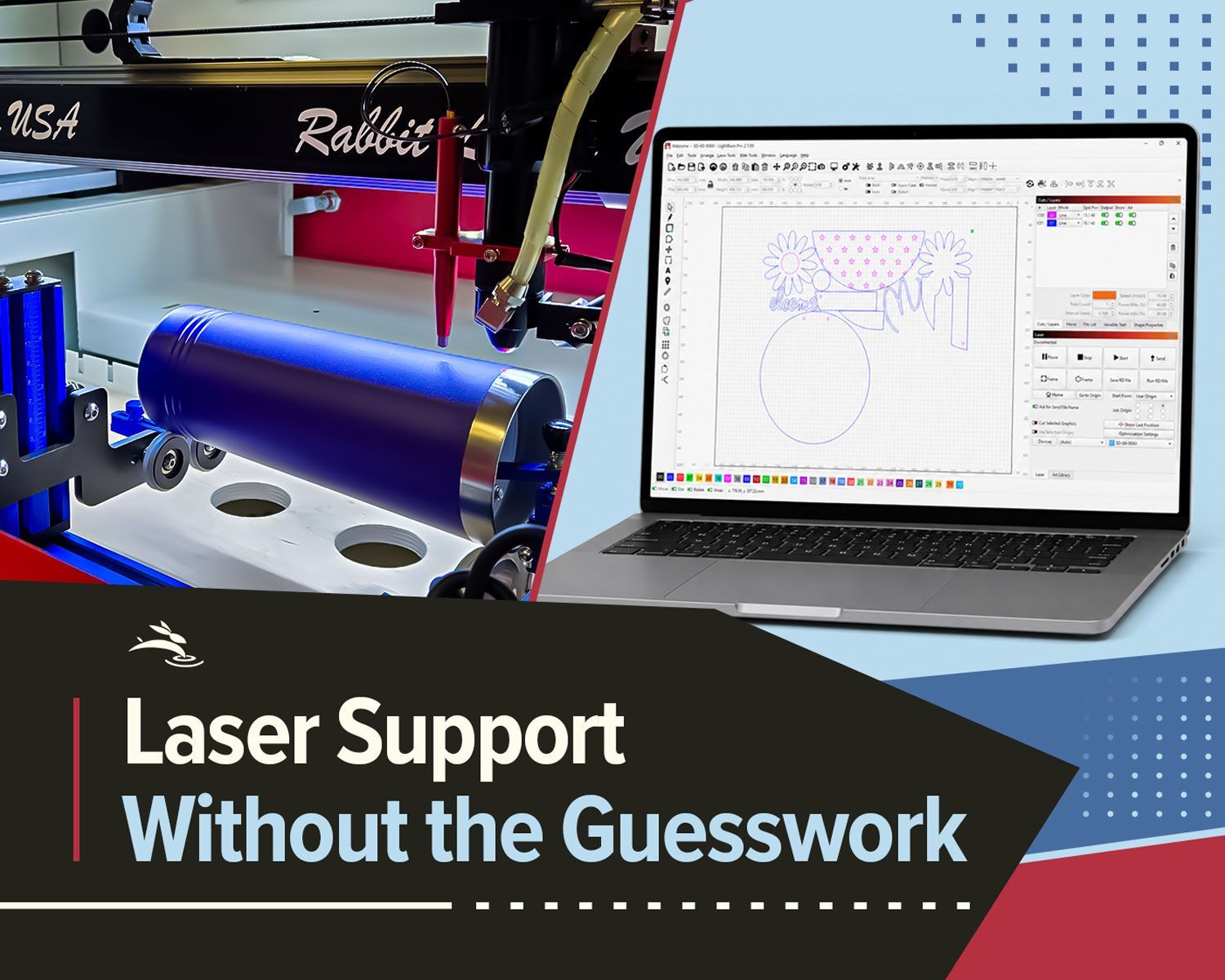
Remote laser support can help with software, settings, troubleshooting, alignment, parts questions, and service needs.
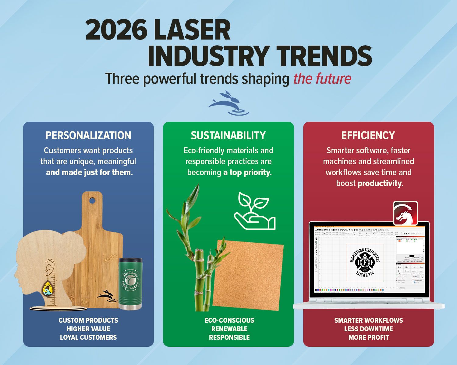
Explore 2026 laser engraving trends, including custom products, eco-friendly materials, efficient workflows, and business growth ideas.
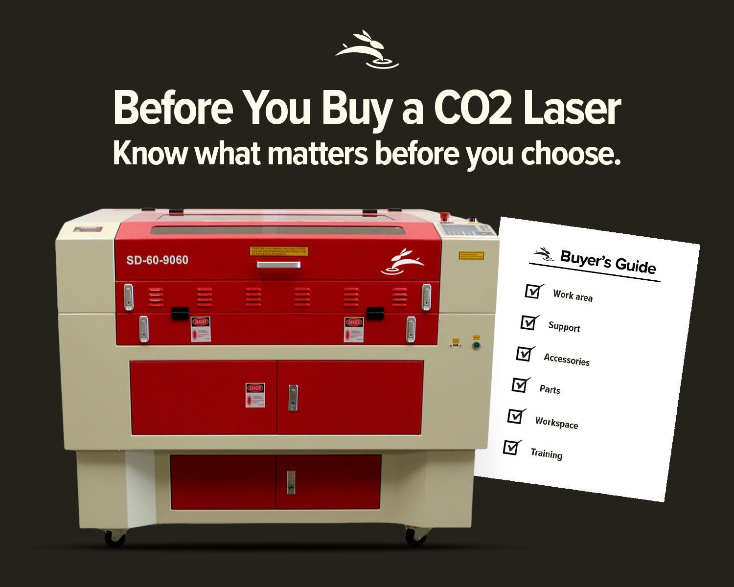
Avoid common CO2 laser buying regrets. Learn what to know about size, support, parts, accessories, setup, and long-term value before you buy.
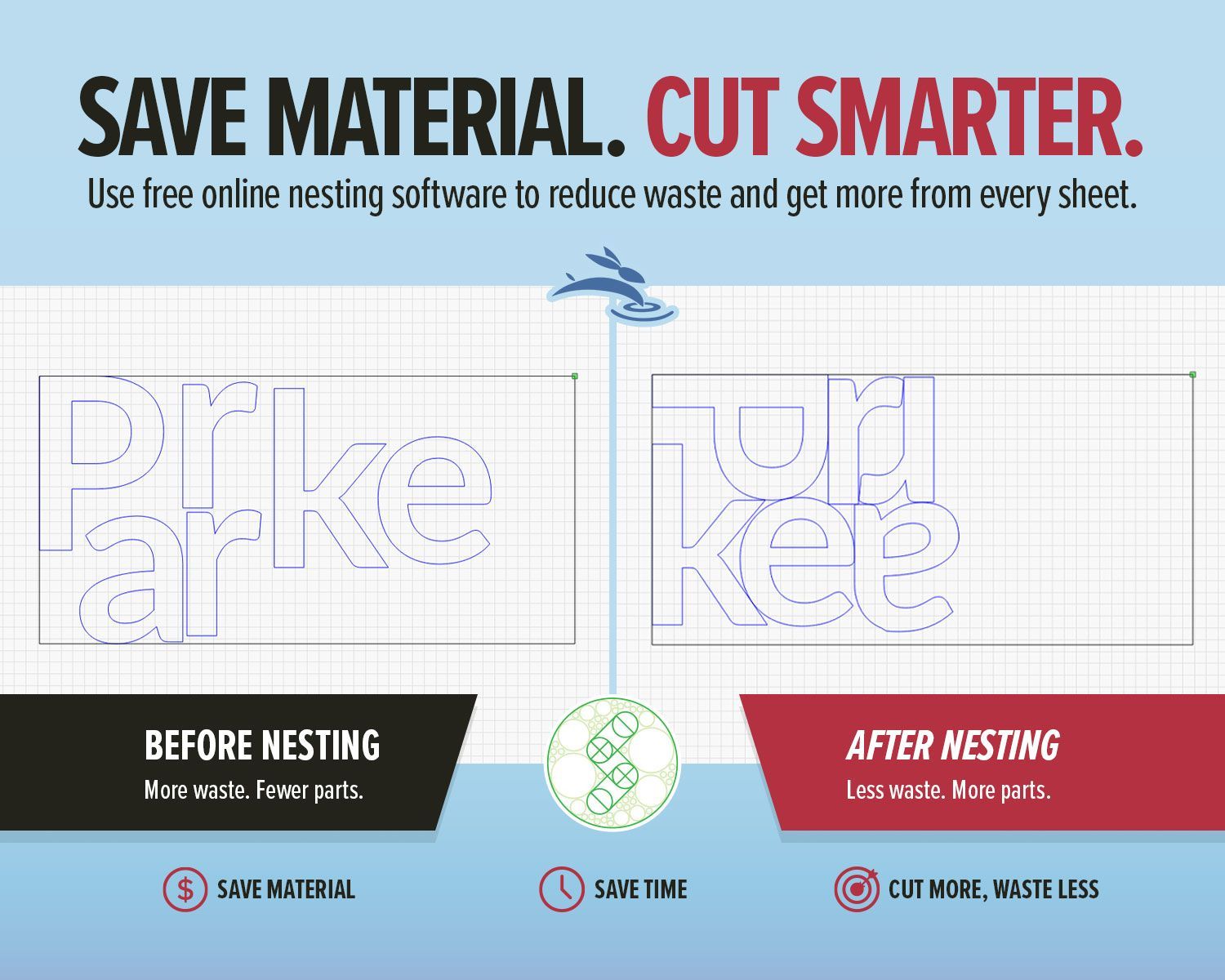
Use free online nesting software like SVGnest to arrange laser cutting files, reduce material waste, and improve your LightBurn workflow.
New to laser engraving or cutting? Avoid common mistakes that cause poor results, wasted material, and frustration. Learn what to fix fast.
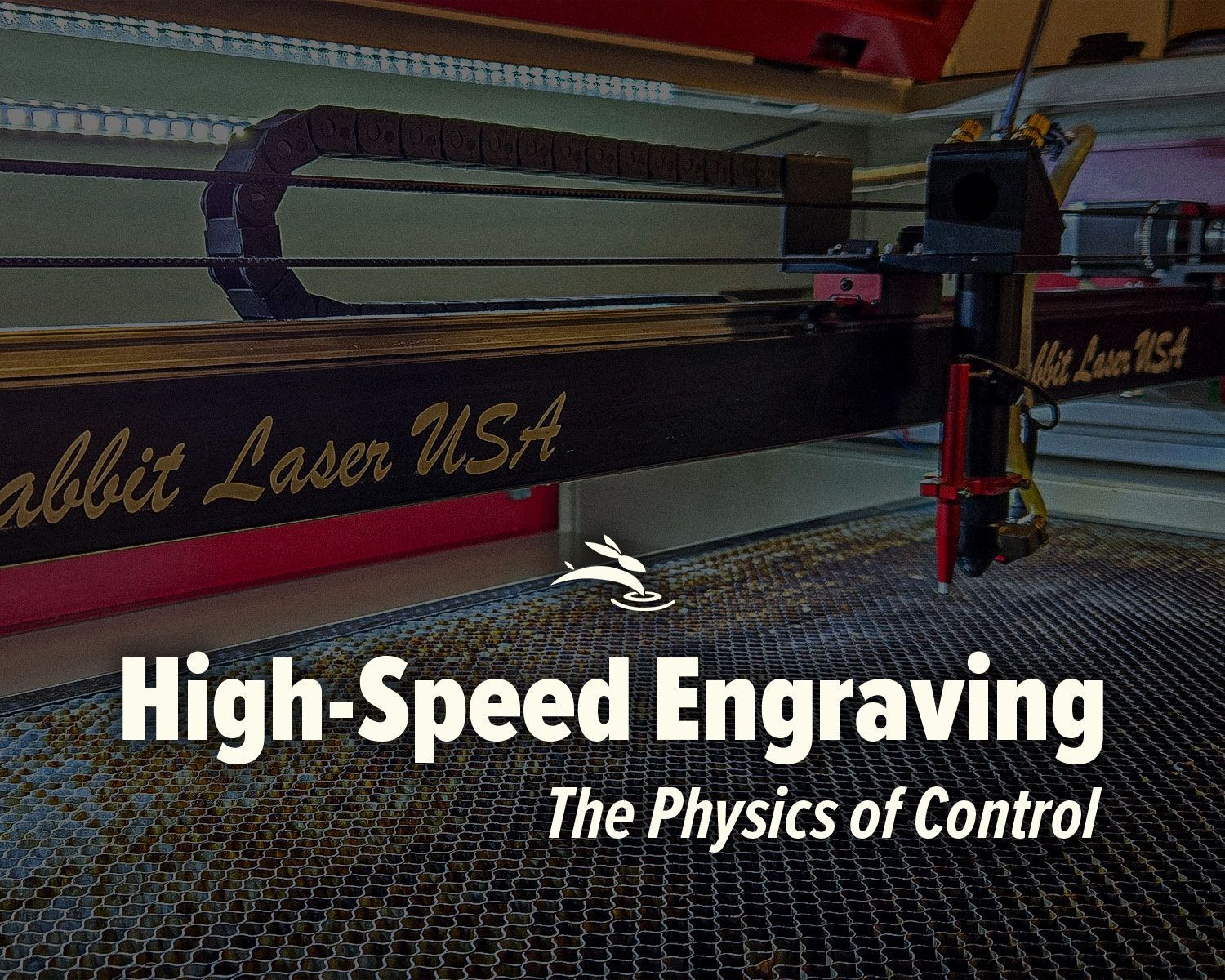
High-speed laser engraving demands motion control. Learn how overscan, acceleration, and momentum impact precision and usable workspace.
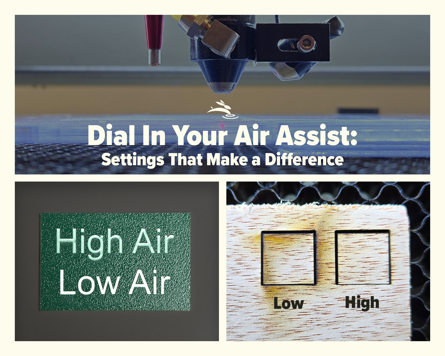
Dial In Your Air Assist: Settings That Make a Difference Air Assist Isn’t Just an Add-On If you’ve ever smelled smoke during a job or noticed charred edges on your laser-cut pieces, chances are your air assist wasn’t doing its job—or it wasn’t set right for your application. While it might seem like a minor detail, air assist plays a critical role in the performance and lifespan of your CO2 laser machine. In this post, we’ll break down the difference between low flow and high flow air assist, when to use each, and how to get the best results from your setup.
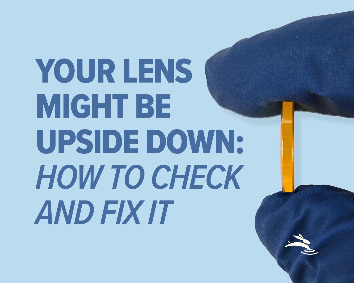
Blurry engraving or weak cuts? Learn the correct CO2 laser lens orientation and how to fix one of the most common laser setup mistakes.
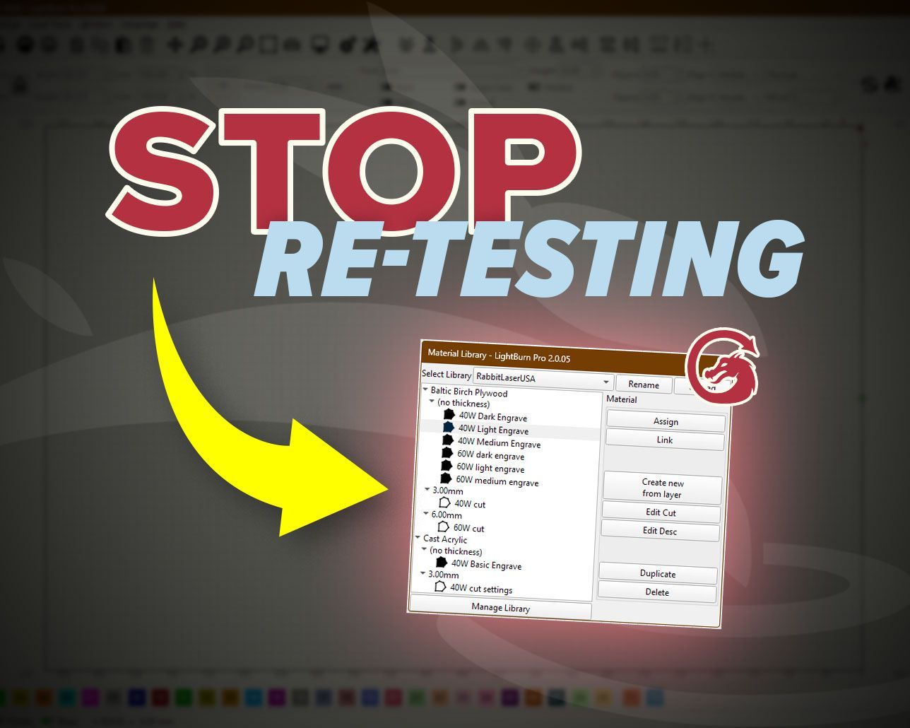
Stop re-testing. Save proven engraving and cutting settings in LightBurn’s Material Library and apply them fast on future projects.
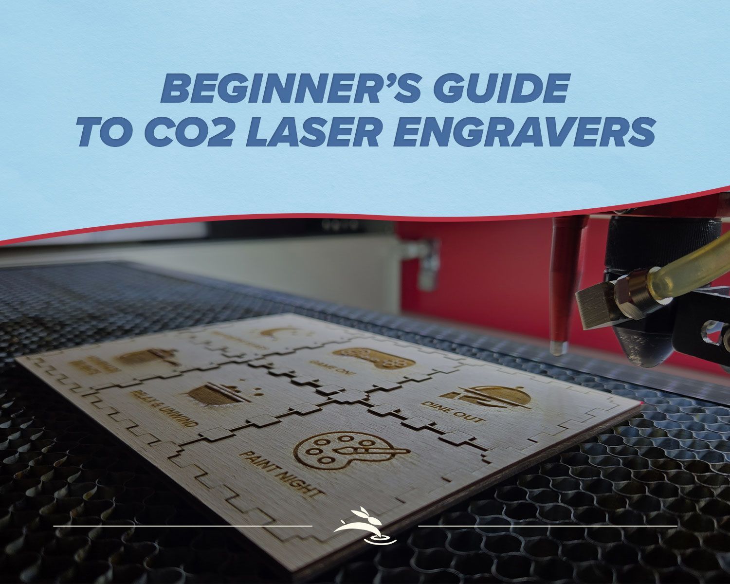
New to CO2 laser engraving? Learn how to choose bed size, wattage, safety features, and support so your first industrial laser is ready to make money.
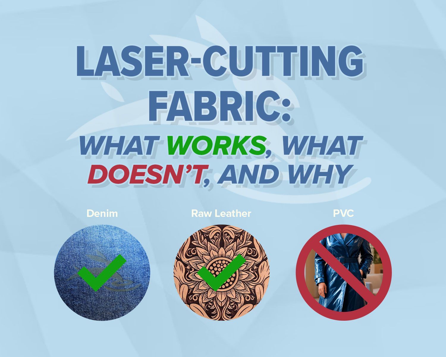
Learn which fabrics are safe to laser cut, which should never be used, and how to get clean results without fraying or burning.