
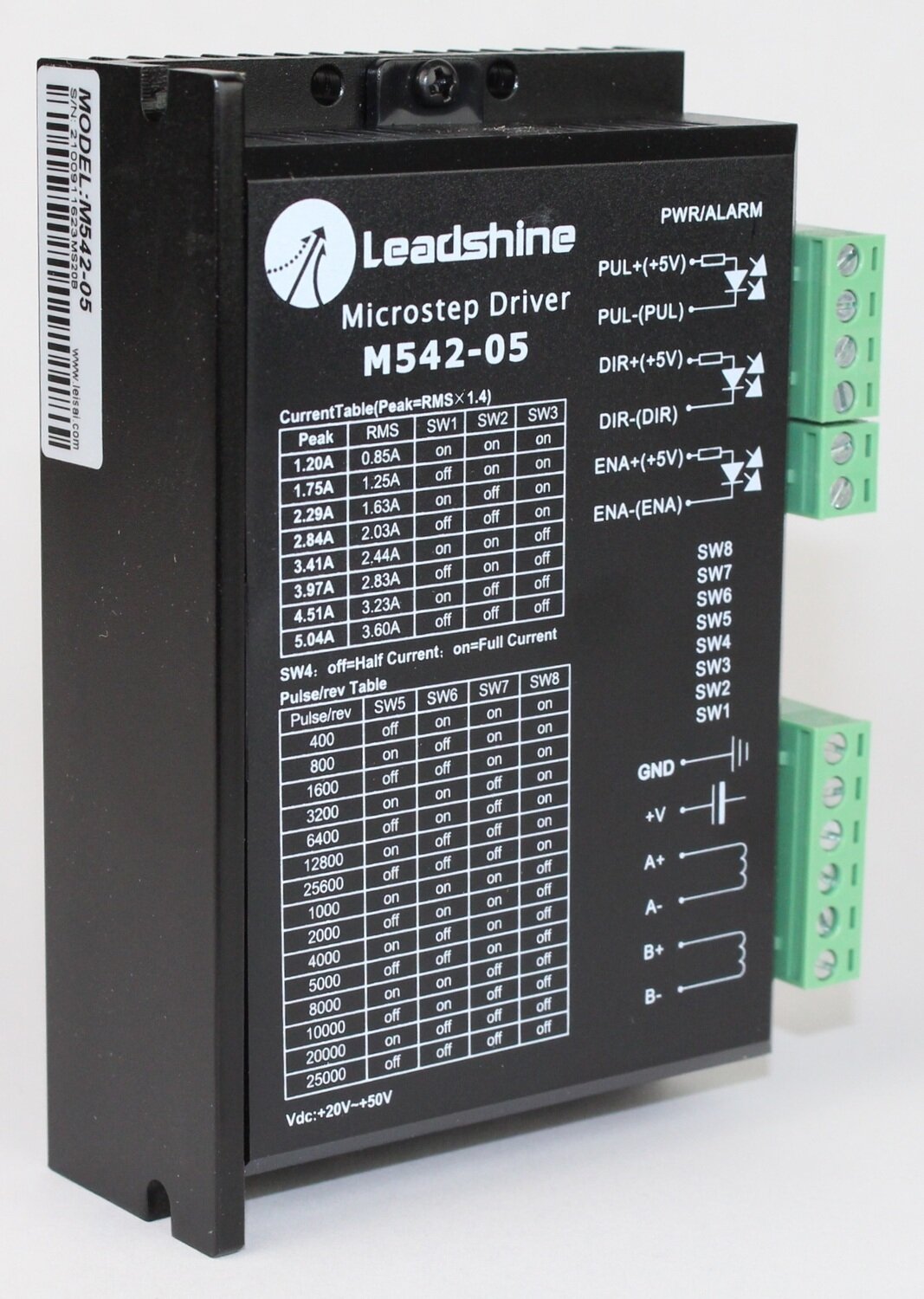
SMD-M542-05 Bipolar Microstep Stepper Motor Driver – 20–50VDC
M542-05 Bipolar Microstep Stepper Motor Driver
Restore smooth, controlled axis movement in a compatible laser engraving or cutting machine with the M542-05 stepper motor driver.
The M542-05 receives pulse and direction commands from the machine controller and converts them into controlled electrical current for a connected stepper motor. This allows the motor to move the laser gantry or machine axis in small, repeatable steps.
Adjustable motor-current and pulse-per-revolution settings allow the driver to be matched to the machine’s stepper motor and motion-control configuration. Correct setup helps provide smooth movement, accurate positioning, proper torque, and controlled motor temperatures.
Key Features
- Bipolar microstep motor driver
- 20–50VDC power input
- Compatible with suitable two-phase and four-phase stepper motors
- Eight selectable motor-current settings
- Current range of 0.85–3.60A RMS
- Corresponding peak-current range of 1.20–5.04A
- Fifteen selectable pulse-per-revolution settings
- Resolution settings from 400 to 25,600 pulses per revolution
- Pulse, direction, and enable control inputs
- +5V control-signal connections
- Four-wire bipolar motor output
- Selectable half or full idle current
- Power and alarm status indicator
- Optically isolated control inputs
- Integrated aluminum heat sink
- Removable terminal connectors included
Motor-Current Settings
The current table printed on the M542-05 lists both peak and RMS current values.
The peak-current value is approximately 1.4 times the RMS value. DIP switches SW1 through SW3 are used to select the motor operating current.
| Peak Current | RMS Current | SW1 | SW2 | SW3 |
|---|---|---|---|---|
| 1.20A | 0.85A | ON | ON | ON |
| 1.75A | 1.25A | OFF | ON | ON |
| 2.29A | 1.63A | ON | OFF | ON |
| 2.84A | 2.03A | OFF | OFF | ON |
| 3.41A | 2.44A | ON | ON | OFF |
| 3.97A | 2.83A | OFF | ON | OFF |
| 4.51A | 3.23A | ON | OFF | OFF |
| 5.04A | 3.60A | OFF | OFF | OFF |
The selected current must match the requirements of the connected motor.
A current setting that is too low may result in weak movement, stalling, or missed steps. A setting that is too high may cause excessive heat and shorten the life of the motor or driver.
SW4 Idle-Current Setting
SW4 controls the amount of holding current supplied when the motor is stopped.
- SW4 OFF: Half current
- SW4 ON: Full current
The half-current setting can reduce motor heat while the axis is idle. A replacement driver should normally be configured to match the original driver unless the motor requirements have been properly verified.
Pulse-Per-Revolution Settings
The M542-05 provides fifteen selectable pulse-per-revolution settings using DIP switches SW5 through SW8.
| Pulses per Revolution | SW5 | SW6 | SW7 | SW8 |
|---|---|---|---|---|
| 400 | OFF | ON | ON | ON |
| 800 | ON | OFF | ON | ON |
| 1,600 | OFF | OFF | ON | ON |
| 3,200 | ON | ON | OFF | ON |
| 6,400 | OFF | ON | OFF | ON |
| 12,800 | ON | OFF | OFF | ON |
| 25,600 | OFF | OFF | OFF | ON |
| 1,000 | ON | ON | ON | OFF |
| 2,000 | OFF | ON | ON | OFF |
| 4,000 | ON | OFF | ON | OFF |
| 5,000 | OFF | OFF | ON | OFF |
| 8,000 | ON | ON | OFF | OFF |
| 10,000 | OFF | ON | OFF | OFF |
| 20,000 | ON | OFF | OFF | OFF |
| 25,000 | OFF | OFF | OFF | OFF |
The pulse-per-revolution setting determines how many controller pulses are required for one complete motor revolution.
The replacement driver should normally use the same SW5 through SW8 positions as the original driver. Changing this setting without updating the machine controller can cause incorrect travel distances and positioning.
Control-Signal Terminals
The control terminals shown on the driver are:
- PUL+ (+5V): Positive step-pulse connection
- PUL− (PUL): Step-pulse signal connection
- DIR+ (+5V): Positive direction connection
- DIR− (DIR): Direction-signal connection
- ENA+ (+5V): Positive enable connection
- ENA− (ENA): Enable-signal connection
The enable terminals may not be used in every machine configuration. Match the replacement wiring to the original driver and machine controller.
Power and Motor Terminals
The power and motor terminals shown on the driver are:
- GND: DC power-supply ground
- +V: Positive DC power input
- A+: Motor phase A positive
- A−: Motor phase A negative
- B+: Motor phase B positive
- B−: Motor phase B negative
The input power supply must remain within the printed range of 20–50VDC.
The motor wires must be connected as the correct A and B phase pairs. Incorrect phase wiring may cause vibration, rough movement, excessive noise, movement in the wrong direction, or failure to rotate.
Product Specifications
- Model: M542-05
- Part number: SMD-M542-05
- Manufacturer: Leadshine
- Product type: Bipolar microstep motor driver
- Input voltage: 20–50VDC
- Current settings: Eight
- RMS current range: 0.85–3.60A
- Peak-current range: 1.20–5.04A
- Pulse-per-revolution settings: Fifteen
- Resolution range: 400–25,600 pulses per revolution
- Control inputs: Pulse, direction, and enable
- Control-signal voltage shown:+5V
- Motor outputs: A+, A−, B+, and B−
- Motor connection: Four-wire bipolar
- Idle-current selection: Half or full current
- Power input terminals:+V and GND
- Status indicator: Power and alarm
- Maximum pulse-input frequency: Up to 300kHz
- Approximate dimensions: 4.65 × 2.97 × 1.30 inches
- Approximate weight: 10 ounces
- Heat sink and connectors: Included
Compatibility Notice
Stepper motor drivers that look similar may have different voltage ranges, current tables, pulse settings, signal requirements, terminal arrangements, or DIP-switch functions.
Before ordering, compare the following with the original driver:
- M542-05 model number
- 20–50VDC input requirement
- Peak and RMS current settings
- SW1 through SW4 positions
- Pulse-per-revolution setting
- SW5 through SW8 positions
- PUL, DIR, and ENA terminal arrangement
- Motor phase connections
- Physical dimensions
- Mounting-hole locations
Do not select a replacement based only on the enclosure shape or the general M542 model name.
Important Installation Information
Disconnect the laser machine from electrical power before inspecting or replacing the stepper motor driver.
Photograph and label every wire and DIP-switch position before removing the original unit. Copying the original switch settings is usually the safest starting point when installing a direct replacement.
Confirm the positive and negative power connections before applying power. Reversing the DC input polarity may immediately damage the driver.
Never connect or disconnect the stepper motor while the driver is powered. Doing so may damage the driver’s output circuitry.
Securely mount the driver with enough open space for heat to escape from the aluminum heat sink. After installation, test the axis at a low speed before returning the machine to normal operation.
Troubleshooting a Motion Problem
Stepper-driver problems may cause symptoms such as:
- An axis that does not move
- A motor that vibrates without rotating
- Jerky or uneven movement
- Missed steps
- Incorrect positioning
- Movement in only one direction
- Excessive motor or driver heat
- An illuminated alarm indicator
- Intermittent axis operation
These symptoms do not always mean the driver has failed. Similar problems may be caused by incorrect DIP-switch settings, loose wiring, damaged motor cables, incorrect phase pairing, a failing DC power supply, mechanical binding, controller problems, or a damaged stepper motor.
Confirm Compatibility Before Ordering
Not sure whether the M542-05 is correct for your laser machine? Contact Rabbit Laser USA with your machine model and clear photos of the original driver, wiring terminals, and DIP-switch positions. Our technical support team can help confirm compatibility before you order.